In this post we are going to modify the configuration that was pushed to the devices in part four. we are going to add a new VLAN and subnet to the each of the leaf switches. We do not have to update the python code. We just have to add the data to our yaml files, which in a production environment could be a database, an IPAM server for example.
Updated Topology
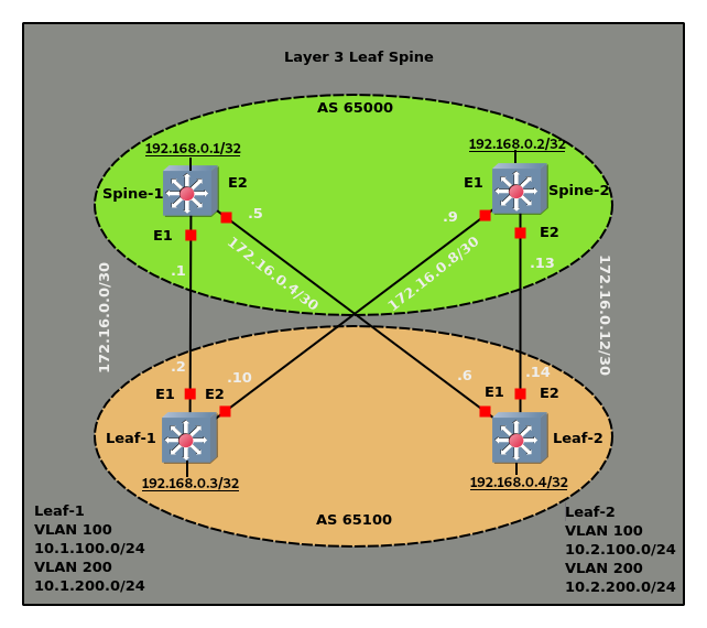
We are going to add VLAN 200 to both leafs. With the VLAN interface ip address 10.1.200.1/24 for leaf-1 and 10.2.200.1/24
for leaf-2. We also have to update our route maps to allow the new subnets to be redistributed. Finally we need an access interface so that the vlan interface comes up.
We will start by adding VLAN 200 and the access interface configuration to leaf.yaml
leaf.yaml
---

vlans:
  - number: 100
    description: Servers1
  - number: 200
    description: Servers2
accessinterfaces:
  - number: 9
    switchport: access
    vlan: 100
  - number: 10
    switchport: access
    vlan: 200

  --snip--
Since this is a shared file, vlan 200 and the access ports will be created on both leaf switches. This is the desired behavior in my case, but the VLANs and/or access ports could always be filtered via an if statement or added to the individual host settings.
The other file we need to modify is hosts.yaml. We are going to add the vlan interfaces and modify the prefix lists.
hosts.yaml
---

--snip--

leaf-1:

--snip--

  routemaps:
    - name: ROUTE-MAP-OUT
      direction: out
  prefixlists:
    - name: PREFIX-LIST-OUT
      action: permit
      sequence: 10
      ip: 192.168.0.3/32
    - name: PREFIX-LIST-OUT
      action: permit
      sequence: 20
      ip: 172.16.0.0/16
    - name: PREFIX-LIST-OUT
      action: permit
      sequence: 30
      ip: 10.1.100.0/24
    - name: PREFIX-LIST-OUT
      action: permit
      sequence: 40
      ip: 10.1.200.0/24
  vlaninterfaces:
    - number: 100
      description: Servers1
      mtu: 9214
      ip: 10.1.100.1/24
      arptimeout: 900
    - number: 200
      description: Servers2
      ip: 10.1.200.1/24
      arptimeout: 900

leaf-2:

--snip--

  routemaps:
    - name: ROUTE-MAP-OUT
      direction: out
  prefixlists:
    - name: PREFIX-LIST-OUT
      action: permit
      sequence: 10
      ip: 192.168.0.4/32
    - name: PREFIX-LIST-OUT
      action: permit
      sequence: 20
      ip: 172.16.0.0/16
    - name: PREFIX-LIST-OUT
      action: permit
      sequence: 30
      ip: 10.2.100.0/24
    - name: PREFIX-LIST-OUT
      action: permit
      sequence: 40
      ip: 10.2.200.0/24
  vlaninterfaces:
    - number: 100
      description: Servers1
      mtu: 9214
      ip: 10.2.100.1/24
      arptimeout: 900
    - number: 200
      description: Servers2
      ip: 10.2.200.1/24
      arptimeout: 900
That is all we need to do. The template file created in part three will take care of adding the new data to the configuration candidate files when it loops through the yaml files.
Now when we run configureleafspine.py the following diffs are found and committed to the switches.
leaf-1 Diffs:

@@ -23,6 +23,9 @@
 !
 vlan 100
    name Servers1
+!
+vlan 200
+   name Servers2
 !
 vrf definition management
 !
@@ -61,6 +64,10 @@
    spanning-tree bpduguard enable
 !
 interface Ethernet10
+   switchport access vlan 200
+   no snmp trap link-status
+   spanning-tree portfast
+   spanning-tree bpduguard enable
 !
 interface Ethernet11
 !
@@ -79,6 +86,11 @@
    ip address 10.1.100.1/24
    arp timeout 900
 !
+interface Vlan200
+   description Servers2
+   ip address 10.1.200.1/24
+   arp timeout 900
+!
 ip route vrf management 0.0.0.0/0 198.51.100.1
 !
 ip routing
@@ -87,6 +99,7 @@
 ip prefix-list PREFIX-LIST-OUT seq 10 permit 192.168.0.3/32
 ip prefix-list PREFIX-LIST-OUT seq 20 permit 172.16.0.0/16
 ip prefix-list PREFIX-LIST-OUT seq 30 permit 10.1.100.0/24
+ip prefix-list PREFIX-LIST-OUT seq 40 permit 10.1.200.0/24
 !
 route-map ROUTE-MAP-OUT permit 10
    match ip address prefix-list PREFIX-LIST-OUT
leaf-2 Diffs:

@@ -23,6 +23,9 @@
 !
 vlan 100
    name Servers1
+!
+vlan 200
+   name Servers2
 !
 vrf definition management
 !
@@ -61,6 +64,10 @@
    spanning-tree bpduguard enable
 !
 interface Ethernet10
+   switchport access vlan 200
+   no snmp trap link-status
+   spanning-tree portfast
+   spanning-tree bpduguard enable
 !
 interface Ethernet11
 !
@@ -79,6 +86,11 @@
    ip address 10.2.100.1/24
    arp timeout 900
 !
+interface Vlan200
+   description Servers2
+   ip address 10.2.200.1/24
+   arp timeout 900
+!
 ip route vrf management 0.0.0.0/0 198.51.100.1
 !
 ip routing
@@ -87,6 +99,7 @@
 ip prefix-list PREFIX-LIST-OUT seq 10 permit 192.168.0.4/32
 ip prefix-list PREFIX-LIST-OUT seq 20 permit 172.16.0.0/16
 ip prefix-list PREFIX-LIST-OUT seq 30 permit 10.2.100.0/24
+ip prefix-list PREFIX-LIST-OUT seq 40 permit 10.2.200.0/24
 !
 route-map ROUTE-MAP-OUT permit 10
    match ip address prefix-list PREFIX-LIST-OUT
leaf-1#show ip route bgp

VRF: default
Codes: C - connected, S - static, K - kernel,
       O - OSPF, IA - OSPF inter area, E1 - OSPF external type 1,
       E2 - OSPF external type 2, N1 - OSPF NSSA external type 1,
       N2 - OSPF NSSA external type2, B I - iBGP, B E - eBGP,
       R - RIP, I L1 - IS-IS level 1, I L2 - IS-IS level 2,
       O3 - OSPFv3, A B - BGP Aggregate, A O - OSPF Summary,
       NG - Nexthop Group Static Route, V - VXLAN Control Service,
       DH - Dhcp client installed default route

 B E    10.2.100.0/24 [20/0] via 172.16.0.1, Ethernet1
                             via 172.16.0.9, Ethernet2
 B E    10.2.200.0/24 [20/0] via 172.16.0.1, Ethernet1
                             via 172.16.0.9, Ethernet2
 B E    172.16.0.4/30 [20/0] via 172.16.0.9, Ethernet2
 B E    172.16.0.12/30 [20/0] via 172.16.0.1, Ethernet1
 B E    192.168.0.1/32 [20/0] via 172.16.0.1, Ethernet1
 B E    192.168.0.2/32 [20/0] via 172.16.0.9, Ethernet2
 B E    192.168.0.4/32 [20/0] via 172.16.0.1, Ethernet1
                              via 172.16.0.9, Ethernet2
leaf-2#show ip route bgp

VRF: default
Codes: C - connected, S - static, K - kernel,
       O - OSPF, IA - OSPF inter area, E1 - OSPF external type 1,
       E2 - OSPF external type 2, N1 - OSPF NSSA external type 1,
       N2 - OSPF NSSA external type2, B I - iBGP, B E - eBGP,
       R - RIP, I L1 - IS-IS level 1, I L2 - IS-IS level 2,
       O3 - OSPFv3, A B - BGP Aggregate, A O - OSPF Summary,
       NG - Nexthop Group Static Route, V - VXLAN Control Service,
       DH - Dhcp client installed default route

 B E    10.1.100.0/24 [20/0] via 172.16.0.5, Ethernet1
                             via 172.16.0.13, Ethernet2
 B E    10.1.200.0/24 [20/0] via 172.16.0.5, Ethernet1
                             via 172.16.0.13, Ethernet2
 B E    172.16.0.0/30 [20/0] via 172.16.0.13, Ethernet2
 B E    172.16.0.8/30 [20/0] via 172.16.0.5, Ethernet1
 B E    192.168.0.1/32 [20/0] via 172.16.0.5, Ethernet1
 B E    192.168.0.2/32 [20/0] via 172.16.0.13, Ethernet2
 B E    192.168.0.3/32 [20/0] via 172.16.0.5, Ethernet1
                              via 172.16.0.13, Ethernet2
Looks like everything is working. Just to be sure.
leaf-1#ping 10.2.200.1 source 10.1.100.1
PING 10.2.200.1 (10.2.200.1) from 10.1.100.1 : 72(100) bytes of data.
80 bytes from 10.2.200.1: icmp_seq=1 ttl=63 time=24.2 ms
80 bytes from 10.2.200.1: icmp_seq=2 ttl=63 time=27.3 ms
80 bytes from 10.2.200.1: icmp_seq=3 ttl=63 time=25.9 ms
80 bytes from 10.2.200.1: icmp_seq=4 ttl=63 time=22.5 ms
80 bytes from 10.2.200.1: icmp_seq=5 ttl=63 time=20.4 ms

--- 10.2.200.1 ping statistics ---
5 packets transmitted, 5 received, 0% packet loss, time 100ms
rtt min/avg/max/mdev = 20.431/24.118/27.343/2.448 ms, pipe 2, ipg/ewma 25.198/2s
In the next part of the series we are going to add a new leaf switch. The code for this part can be found here.